Overblog
Follow this blog Administration + Create my blog
September 9 2014 2 09 /09 /September /2014 04:54

We recommend 1 channel 110V~220V customized delay time controller (S1RD-AC220+C-2). At first, it must be set delay time in advance. According to your own actual requirement, you can set delay time you want. e. g. delay time: 20 seconds. You cannot change delay time once it is set. It is applied for controlling lights, motors, fans, electrically operated door/ lock/windows/ blinds/ cars or other appliances with AC 110~240V or DC 0~28V. You can turn on/off device on the receiver with transmitter from any place within reliable distance (theoretical distance 100m), the wireless RF signal can pass through wall, floors, doors and other obstacles.

time delay remote controller

Wiring:

Initial state: B, C = Normally Open; A, B = Normally Closed.

AC lamp is wired to normally open terminals B&C. And add additional ac power to AC lamp.

circuit

The delay time is set in advance. It is non-adjustable.

Press button 1: Turn on the relay (connect B and C, disconnect A and B)

After delay time, turn off the relay by itself (disconnect B and C, connect A and B)

During the delay time, press button 2: Turn off the relay straightway (disconnect B and C, connect A and B)


Share this post
Repost0
September 2 2014 2 02 /09 /September /2014 09:57

Question from customer:

I am looking for a long range relay to control a water pump. The water pump now is controlled by a float switch (on/off) at the reservoir 800 meters away. I have 120 volts at both locations and a relay to start pump.

Answer:

We recommend the 2000m rf AC receiver (S1PUA-AC220-ANT2) and the long range transmitter CB-2N. The receiver is soldered with external extended antenna, which can make its transmission distance at 2000m/6000ft theoretically. It works between AC 100~240V voltage. The maximum working current is 30amps. There are 315Mhz or 433Mhz at your option. The transmitter is special designed because its triggered method is connection and disconnection of two wires. When two wires are connected, the transmitter is triggered and then transmits an rf signal “ON”. When two wires are disconnected, the transmitter is triggered and then transmits an rf signal “OFF”.

remote-controller_1

The wiring method of your water pump will be talked next.

A, B terminals are normally open; A, C terminals are normally closed. Wire Water pump motor to A terminal and N terminal. Add wire to connect B&L terminals. Supply AC 100~240V power to receiver. Connect two wires of transmitter to relay you mentioned.

circuit

Usage:

When two wires of transmitter are connected, the transmitter is triggered and then transmits rf signal “ON”; When the receiver accepts the signal, it will make water pump work.

When two wires of transmitter are disconnected, the transmitter is triggered and then transmits an rf signal “OFF”. When the receiver accepts the signal, it will stop water pump.

Share this post
Repost0
August 20 2014 3 20 /08 /August /2014 08:53

We recommend this 2 channel power-off memory function remote controller (S2MU-DC06/09/12/24 & C-2). It can work in 4 kinds of voltage, 6V, 9V, 12V and 24V. There 4 working modes in it. You can switch as you want through connection or disconnection of jumpers. It controls lights, motors, fans, electrically operated doors / locks / windows / blinds / cars or other appliances with voltage AC110~240V or DC0~28V. It is great for hard to reach lights or other DC/AC electrical devices. The working transmission is about 100m in the open field. With function of memory, if the power is cut off, the relay will return automatically to the previous status after the power is restored.

remote controller

We’d like to show the wiring and controlling of ac, dc lamps.

The contact of relay of each receiver is normally open/ closed. So you need to wire ac lamp or dc lamp to normally open contact B&C and supply AC 220V power or dc power to lamp.

inner circuit

wiring diagram


Usage:

Setting control mode Toggle: Only connect Jumper-2.

Control mode Toggle: Press -> On; Press again -> Off.

Setting control mode Momentary: Only connect Jumper-1.

Control mode Momentary: Press and hold -> On; Release -> Off.


Setting control mode Latched: Do not connect Jumper-1 and Jumper-2.

Control mode Latched: Press -> On, another relay Off; Press another button -> Off.


Setting control mode Momentary + Toggle: Connect Jumper-1 and Jumper-2.

Control mode Momentary (Channel 1): Press -> On; Press again -> Off.

Control mode Toggle (Channel 2): Press and hold -> On; Release -> Off.


Share this post
Repost0
August 12 2014 2 12 /08 /August /2014 09:46
One of our customers wants a simple wireless remote operate 4 led lamps from several room at his house. He needs 4 transmitters and a receiver which can be mounted in a designated place. The remote must work from receiver about 50m away and not line of sight through doors and walls.
We suggest him choose dc 4 channel remote control system (S4C-DC12& 4C-1). Maximum working current is 5amp each relay. Working distance of remote and receiver set is about 100m (300ft) in open field. This 4CH 6V9V/12V/24V wireless remote switch operates in toggle, momentary, latched, toggle + momentary control mode (set the mode as you like freely). Easy to install and operate. Just press slightly the button on the remote, you can control universal DC/AC electrical devices. The RF signal can pass through walls, doors and other barriers. As he said, we will set 4 transmitters and this receiver with same 8-bits code in advance so that they can work together.
remote controller
Operation modes:
  • 1) Setting control mode Latched: Disconnect Jumper-1 and Jumper-2.
Control mode Latched (Relay 1~4): Press -> On, other relays Off; Press other button -> Off.
  • 2) Setting control mode Momentary: Only connect Jumper-1.
Control mode Momentary (Relay 1~4): Press and hold -> On; Release -> Off.
  • 3) Setting control mode Toggle: Only connect Jumper-2.
Control mode Toggle (Relay 1~4): Press -> On; Press again -> Off.
  • 4) Setting control mode Momentary + Toggle: Connect Jumper-1 and Jumper-2.
Control mode Momentary (Relay 1, 2): Press and hold -> On; Release -> Off.
Control mode Toggle (Relay 3, 4): Press -> On; Press again -> Off.
We will show you how to remote control 4 led lamps from different places.
Share this post
Repost0
August 5 2014 2 05 /08 /August /2014 10:09

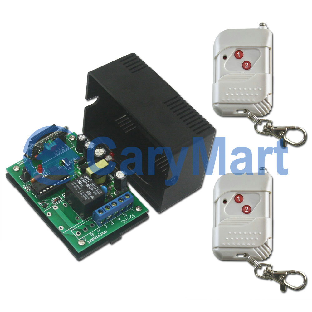
We’d like to recommend one-to-many series remote control system: 15 channel remote control system (S15C-DC12 & 15C-1), which includes 15 transmitters and 1 receiver. The transmitter’s transmission distance is 100/300ft theoretically. This wireless gadget can remote control lights, TVs, motors, fans, cameras, video signals, audio signals, electrical operated doors/locks/windows/blinds/cars or other appliances with voltage of AC 110~240V or DC0~28V.

1_011_03

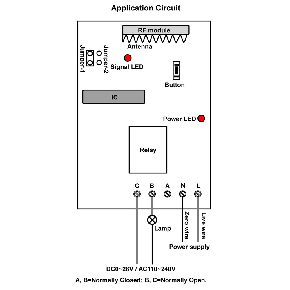
We’d like to show how to wire lamps and remote control lamps with this system.

The initial status is A,B normally open; B,C normally closed. We wire lamps to A&B terminals of each relay one by one. Next, we supply power to receiver. (Supply AC or DC power).

1_07

There are 15 working modes in it. We will try to show you the operation.

1) Learning Momentary control mode: When the receiver is in the status of LEARNING, press transmitter 1.

Control mode Momentary (Channel 1~15): Press and hold -> On; Release -> Off.

Press and hold transmitter 1: Turn on relay 1 (connect A and B, disconnect B and C)

Release transmitter 1: Turn off relay 1 (disconnect A and B, connect B and C)

Press and hold transmitter 15: Turn on relay 15 (connect A and B, disconnect B and C)

Release transmitter 15: Turn off relay 15 (disconnect A and B, connect B and C)

2) Learning Latched control mode: When the receiver is in the status of LEARNING, press transmitter 2.

Control mode Latched (Channel 1~15): Press -> On, other relays Off; Press other button -> Off.

Press transmitter 1: Turn on relay 1 (connect A and B, disconnect B and C)

Turn off other relays (disconnect A and B, connect B and C)

Press transmitter 15: Turn on relay 15 (connect A and B, disconnect B and C)

Turn off other relays (disconnect A and B, connect B and C)

3) Learning Toggle control mode: When the receiver is in the status of LEARNING, press transmitter 3.

Control mode Toggle (Channel 1~15): Press -> On; Press again -> Off.

Press transmitter 1: Turn on relay 1 (connect A and B, disconnect B and C)

Press transmitter 1 again: Turn off relay 1 (disconnect A and B, connect B and C)

Press transmitter 15: Turn on relay 12 (connect A and B, disconnect B and C)

Press transmitter 15 again: Turn off relay 12 (disconnect A and B, connect B and C)

4) Learning Momentary (Channel 1~8) + Latched (Channel 9~15) control mode: When the receiver is in the status of LEARNING, press transmitter 4.

5) Learning Toggle (Channel 1~8)) + Momentary (Channel 9~15) control mode: When the receiver is in the status of LEARNING, press transmitter 5l.

6) Learning Latched (Channel 1~8) + Toggle (Channel 9~15) control mode: When the receiver is in the status of LEARNING, press transmitter 6.

7) Learning Momentary (Channel 1~13) + Latched (Channel 14~15) control mode: When the receiver is in the status of LEARNING, press transmitter 7.

8) Learning Toggle (Channel 1~13) + Momentary (Channel 14~15) control mode: When the receiver is in the status of LEARNING, press transmitter 8.

9) Learning Toggle (Channel 1~5) + Momentary (Channel 6~10) + Latched (Channel 11~15) control mode: When the receiver is in the status of LEARNING, press transmitter 9.

10) Learning Momentary (Channel 1~5) + Latched (Channel 6~10) + Momentary (Channel 11~15) control mode: When the receiver is in the status of LEARNING, press transmitter 10.

11) Learning Toggle (Channel 1~2) + Momentary (Channel 3~10) + Latched (Channel 11~15) control mode: When the receiver is in the status of LEARNING, press transmitter 11.

12) Learning Momentary (Channel 1~2) + Toggle (Channel 3~10) + Latched (Channel 11~15) control mode: When the receiver is in the status of LEARNING, press transmitter 12.

13) Learning Latched (Channel 1~2) + Momentary (Channel 3~10) + Toggle (Channel 11~15) control mode: When the receiver is in the status of LEARNING, press transmitter 13.

14) Learning Toggle (Channel 1~2) + Latched (Channel 3~9) + Momentary (Channel 10~15) control mode: When the receiver is in the status of LEARNING, press transmitter 14.

15) Learning Toggle (Channel 1~13) + All On / Off (Channel 14/15): When the receiver is in the status of LEARNING, press butt transmitter on 15.

Press transmitter 14: Turn on all 15 relays

Press transmitter 15: Turn off all 15 relays

Share this post
Repost0
July 31 2014 4 31 /07 /July /2014 08:37

We are about to recommend remote controller which is applied to both motor and lamp. It is DC12V momentary &toggle remote controller (S1F-DC12 & C-3-2), which features in motor forward-reverse capability. You can rotate the motor in positive or reversal direction by transmitter from any place within a reliable distance, wireless signal pass through walls, floors and doors. It is suitable for the motors of rolling blinds / doors, projection screens, awnings, pumps, winches, conveyors or other appliances and mechanicals with voltage DC12V. We also design lamp controlling function so that you can control motor and lamp with the same transmitter.

remote controller

From the following pictures, we will show you how to remote control motor and lamp.

Connect DC 12V power supply to terminals 1 and 2, connect DC motor to terminals 5 and 6, and connect a light to terminals 3 and 4

Remote Control Wireless Switch & Controllers

wiring

Press button △ and hold: Terminals 5 and 6 output + DC 12V (6: +, 5: -), motor rotates in the positive direction

Release button △: Terminals 5 and 6 no output, motor stops

motor positive rotation

Press button ▽ and hold: Terminals 5 and 6 output - DC 12V (6: -, 5: +), motor rotates in the reversal direction

Release button ▽: Terminals 5 and 6 no output, motor stops

motor reverse rotation

Press button □: Terminals 3 and 4 output DC 12V (3: +, 4: -), turn on the lamp

lamp on

Press button □ again: Terminals 3 and 4 no output, turn off the lamp

lamp off

Share this post
Repost0
July 10 2014 4 10 /07 /July /2014 09:26

Question from customer:

Whether we can get the receivers with different voltage versions? For example 2 piece of 24 volt and 2 piece of 240 volt.

Answer:

Yes, it is possible. We recommend those two kinds of receivers—for 24V version, it is 24V DC input receiver (S2UB-DC24). For 240V version, it is 100V~240V input receiver (S2U-AC220). Both of them have two relays on the PCB. So there are four channels totally for your devices. They can pair up with long range transmitter (CB-4).

remote-controller

It can control lights, motors, fans, electrically operated doors/locks/windows/blinds/cars or other appliances with voltage AC 110~240V or DC 0~28V. Owing to normally open& closed contact, you should add additional power supply to your devices besides your receivers. But you can do as following wiring method to save power supply adaptors. Wire devices (lamps) to B terminals of each relay, using wires to connect devices to output terminals of each receiver. For dc input receiver, we supply dc 24v power; for ac input receiver, we supply ac 240v power.

circuit

There are toggle, momentary, latched and momentary+toggle modes. You want to remote control 4 devices, so you’d better choose toggle or momentary mode or toggle+momentary mode.

Setting control mode Toggle: Only connect Jumper-2.

Control mode Toggle: Press -> On; Press again -> Off.

Press button A: Turn on relay 1 of Receiver 1 (connect B and C, disconnect A and B)

Press button A again: Turn off relay 1 of Receiver 1 (disconnect B and C, connect A and B)

Press button D: Turn on relay 2 of Receiver 2 (connect B and C, disconnect A and B)

Press button D again: Turn off relay 2 of Receiver 2 (disconnect B and C, connect A and B)

Setting control mode Momentary: Only connect Jumper-1.

Control mode Momentary: Press and hold -> On; Release -> Off.

Press and hold button A: Turn on relay 1 of Receiver 1 (connect B and C, disconnect A and B)

Release button A: Turn off relay 1 of Receiver 1 (disconnect B and C, connect A and B)

Press and hold button D: Turn on relay 2 of Receiver 2 (connect B and C, disconnect A and B)

Release button D: Turn off relay 2 of Receiver 2 (disconnect B and C, connect A and B)

Setting control mode Momentary + Toggle: Connect Jumper-1 and Jumper-2.

Control mode Momentary (Channel 1 of Receiver 1, 2): Press and hold -> On; Release -> Off.

Press and hold button A: Turn on relay 1 of Receiver 1 (connect B and C, disconnect A and B)

Release button A: Turn off relay 1 of Receiver 1 (disconnect B and C, connect A and B)

Press and hold button B: Turn on relay 1 of Receiver 2 (connect B and C, disconnect A and B)

Release button B: Turn off relay1 of Receiver 2 (disconnect B and C, connect A and B)

Control mode Toggle (Channel 2 of Receiver 1, 2): Press -> On; Press again -> Off.

Press button C: Turn on relay 2 of Receiver 1 (connect B and C, disconnect A and B)

Press button C again: Turn off relay 2 of Receiver 1 (disconnect B and C, connect A and B)

Press button D: Turn on relay 2 of Receiver 2 (connect B and C, disconnect A and B)

Press button D again: Turn off relay 2 of Receiver 2 (disconnect B and C, connect A and B)

Share this post
Repost0
July 8 2014 2 08 /07 /July /2014 08:34

99-channel Transmitter pairs up with 24 receivers to build a remote control kit (24S1XCB-AC220 & CP-99). It can controls lights, fans, motors, electrically actuated doors/ locks/ windows/ rolling blinds/ cars or other appliance with AC 110~240V. The transmitter adopts singlechip technology to build million of code and has LCD display screen. One transmitter can work with 99 receivers simultaneously.

remote controller-our automation1_10

This kind of remote controller aims at controlling 24 AC Lamps. We will show you the procedure.

circuit-our automation

circuit-diagram

Step 1

Wire each lamp to terminals 1 &5 of each receiver. And supply power to each receiver.

Step 2

The coding type is learning code, so receiver should learn from transmitter at first.

1) Press and hold the button of receiver about 2 seconds until signal LED flashes; then release the button, at this time the receiver enters into status of LEARNING.

2) Press any number button on the transmitter to select a number from 01 to 99, then press button “T” or “M” to send signal. If signal LED immediately turns off, it means learning is successful.

3) The receiver can learn only one channel of the transmitter. So learning code must be one by one till the last one.

Step 3

Press any number button to select a number from 01 to 99 by combination of the number 0~9, then press button “T” (Toggle) or “M” (Momentary) to send signal. LCD screen will displays numbers at the same time, and LCD screen will turn off after 15 seconds if there is no any operation.

Toggle Mode Operation: If you want to send signal of the 24 channel, you can press “2″, then press “4″, next press button “T”, the signal is sent immediately; when you press the button “T” again, the signal will be sent again.

Momentary Mode Operation: If you want to send signal of the 24 channel, you can press “2″, then press “4″, next press and hold button “M”, the signal is continuously sent; when you release the button “M”, the signal will stop.

So we want to remote control 24 AC lamps, we choose Toggle mode.

Press 1+T, send signal to receiver, turn on lamp 1, press T again, turn off lamp 1. (Waiting for LCD screen being off, you can continue next operation every time.)

Press 2+4+T, send signal to receiver, turn on lamp 24, press T again, turn off lamp 24.

Share this post
Repost0
July 3 2014 4 03 /07 /July /2014 08:00

Portable engine generators are used widely to supply electrical power in places where power is not dependable or available, or where power is needed only temporarily. Portable engine generators are sometimes used to supply power at construction sites. When we come across power failure, portable engine generator can supply power to appliances temporarily. Have you ever thought remote controlling portable engine generator? Recently, one of our customers is looking for a remote control for a portable generator which basically has 2 circuits to operate. The first circuit is the run/stop circuit and operates on toggle, the second is the starter circuit and operates on momentary.

portable generator

We recommend the 2 channel ac multi-mode remote control kit (S2U-AC220 & C-2).

This kind of receiver is multi-mode, including toggle, momentary, latched, momentary+toggle mode. You can set one channel operated on toggle, another channel operated on momentary. 10 amps for each channel is the maximum working current. When receiver works with transmitter (C-2), its working distance can reach 100m (300ft).

remote-controller-our-automation

The kit works in toggle, momentary, latched and momentary+toggle modes. You can set momentary+toggle mode according to you need.

Setting control mode Momentary + Toggle: Connect Jumper-1 and Jumper-2.

Control mode Momentary (Channel 1): Press and hold -> On; Release -> Off.

Press and hold button 1: Turn on relay 1 (connect B and C, disconnect A and B)

Release button 1: Turn off relay 1 (disconnect B and C, connect A and B)

Control mode Toggle (Channel 2): Press -> On; Press again -> Off.

Press button 2: Turn on relay 2 (connect B and C, disconnect A and B)

Press button 2 again: Turn off relay 2 (disconnect B and C, connect A and B)

So your wiring must like this.

Wire circuit 1 to relay 2

Wire circuit 2 to relay 1

circuit-diagram

Share this post
Repost0
July 1 2014 2 01 /07 /July /2014 09:15

Question from customer:

“I have a waterfall water feature that currently has an 110v 250W pump that run from 7AM until 10PM. I would like to save more energy by having these pumps turn on by detecting motion near the water feature. 110 degree detection, within 30 feet would be sufficient. The more intelligent, the better (i.e. body/heat/motion/mass detection). There is no need to run a waterfall water feature when no one is there to enjoy it. What do you recommend?”

Fallsview water feature and front entrance

Answer:

We recommend wireless infrared movement detector and receiver with time delay function (S1DA-AC220-ANT2&W-01) to you. This kit is 220V actuated. With external extended antenna, it can work within 6000ft in the open field. With adjustable time delay function, you can adjust delay time from 0 second to 99 hours. The motion detector can detect any movement within 10m. Detection range is fan-shaped angle 110°.

remote controller-our automationmotion detector-our automation

We’d like show you how to use this kit.

Steps:

1 Using screws to fix the bracket on the wall to favorable locations according to your need (i.e. the corridor towards waterfall water feature) and put the detector on the bracket, then adjust the detector to the suitable angle of 10~14° and turn on it.

2 Wire pump motor to B terminals of receiver (A, B = Normally Closed; B, C = Normally Open). Press buttons of “+” and “-” on the timer of receiver, “H” is Hour, “M” is Minute, and “S” is Second. We suggest you that you can set your pump work every 30 minutes from 7AM to 10PM. Once people pass corridor towards waterfall water feature, the motion detector is triggered. You can set “M30”. And supply power to receiver and pump motor.

circuit-our automation

3 When the movement detector is triggered: Turn on relay (connect B and C, disconnect A and B).

The pump motor begins to work. It will last 30 minutes if you set “M30”. After delay time, there is no motions any more, it will turn off by itself.

Share this post
Repost0

Presentation

  • : Coral-Home
  • : Here you will find articles on subjects of home & industrial automation.
  • Contact

Profile

  • RF-Light-Switch
  • I'd like to share ideas about how to remote control home & industrial electrical devices.
  • I'd like to share ideas about how to remote control home & industrial electrical devices.

Archives

Categories